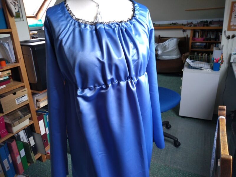
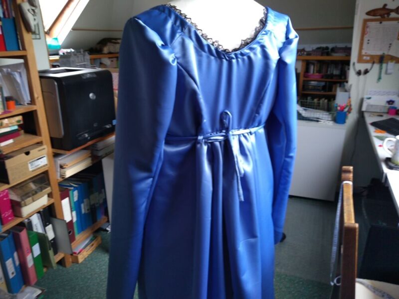
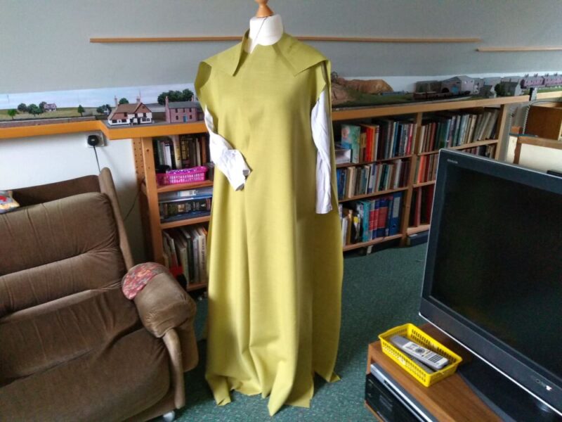
The dress is mostly assembled; the front is a bit lumpy and requires further work, but I am pleased with the back:
Once I am happy with the front, I only need to hem the sleeves and skirt.
Regency Dress nears completion.
Reply

The dress is mostly assembled; the front is a bit lumpy and requires further work, but I am pleased with the back:
Once I am happy with the front, I only need to hem the sleeves and skirt.
One of the things that triggered my “Weather Station” project was a request to build a similar Air Quality Sensor for a friend. This uses the same laser sensor, but a different computer board and temperature/humidity sensor. The kit is around £22 from Ebay.
The first thing to do was to connect up the various bits, flash the firmware and see if it all works:
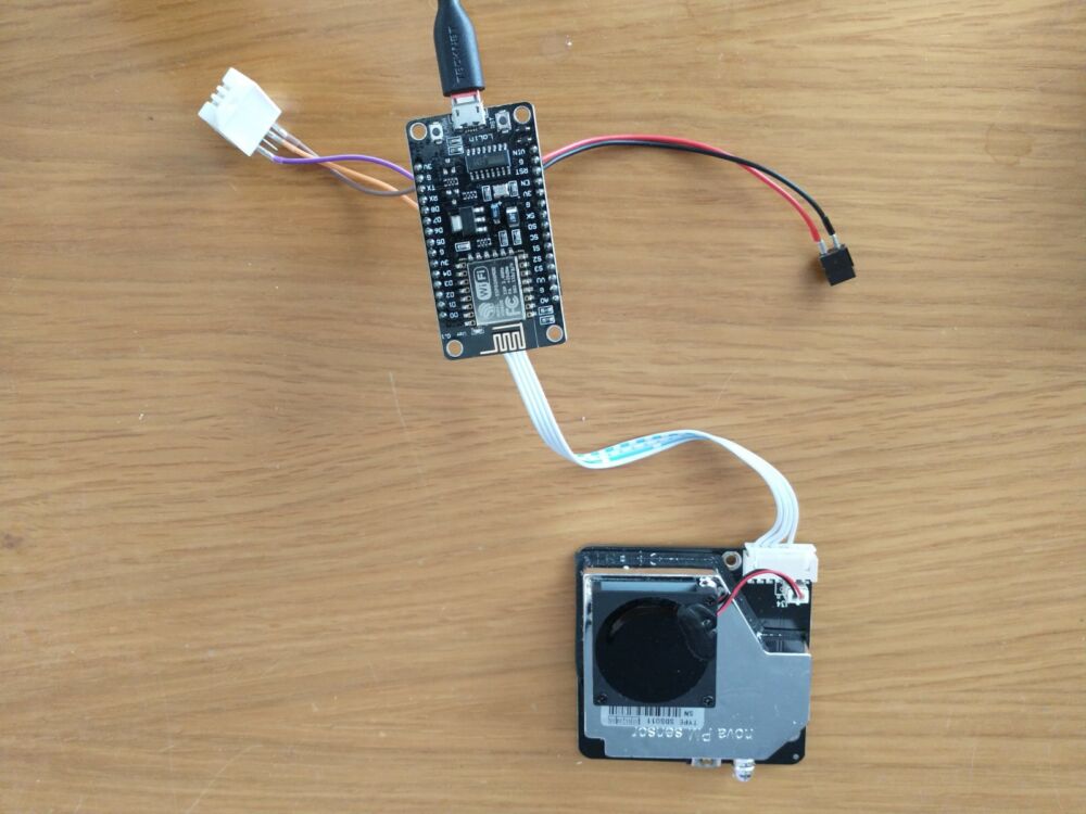
The computer connects to the world via a WiFi connection (the aerial is that little squiggle on the bottom of the computer board) and you use a web browser to configure the system.
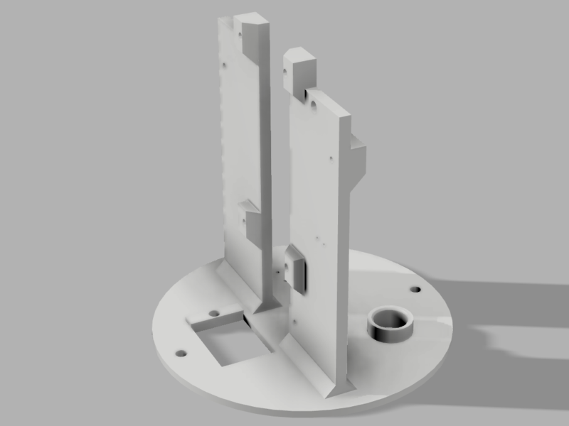
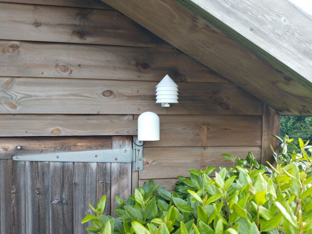
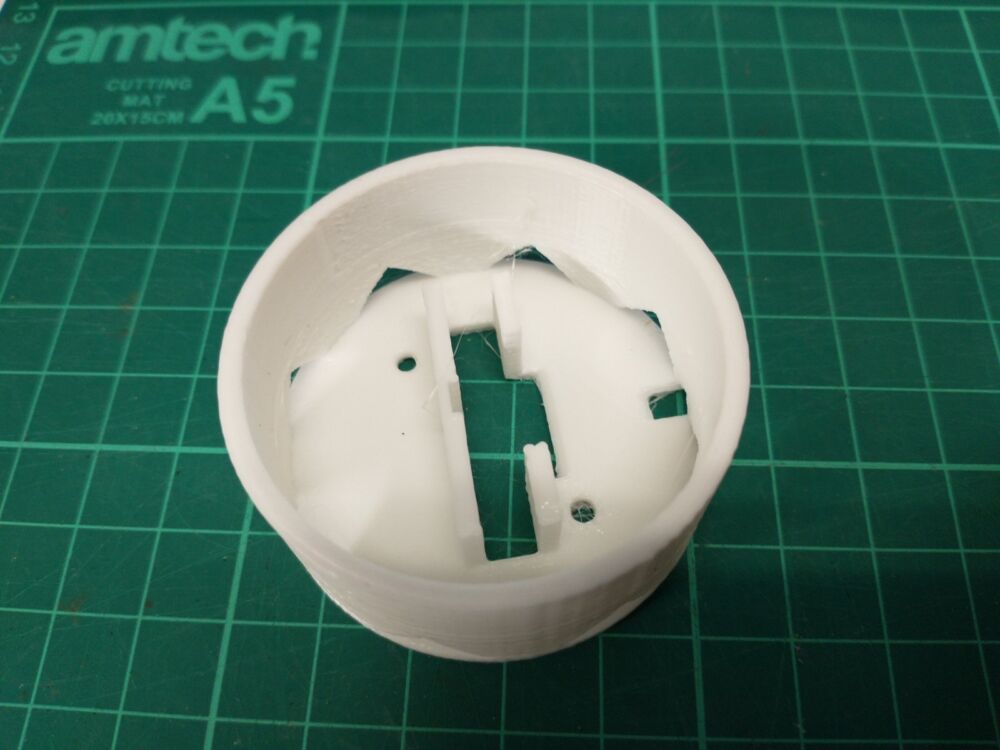
This sensor had to be a neat unit on a wall, and a bit of rummaging around on the internet found a suitable case for this system. Unfortunately, that design mounted the laser sensor “upside down”, which is not recommended by the manufacturer, so I ended up redesigning the internal frame:
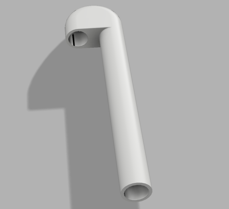
I also had to design and 3D print a ‘tube’ to get the air from the outside world into the sensor – I could have used a plastic tube, but it’s difficult to get that much bend in it. And I didn’t have any…
The SDS011 laser sensor mounts on one side of the vertical frame with the pipe connecting the inlet to the base:
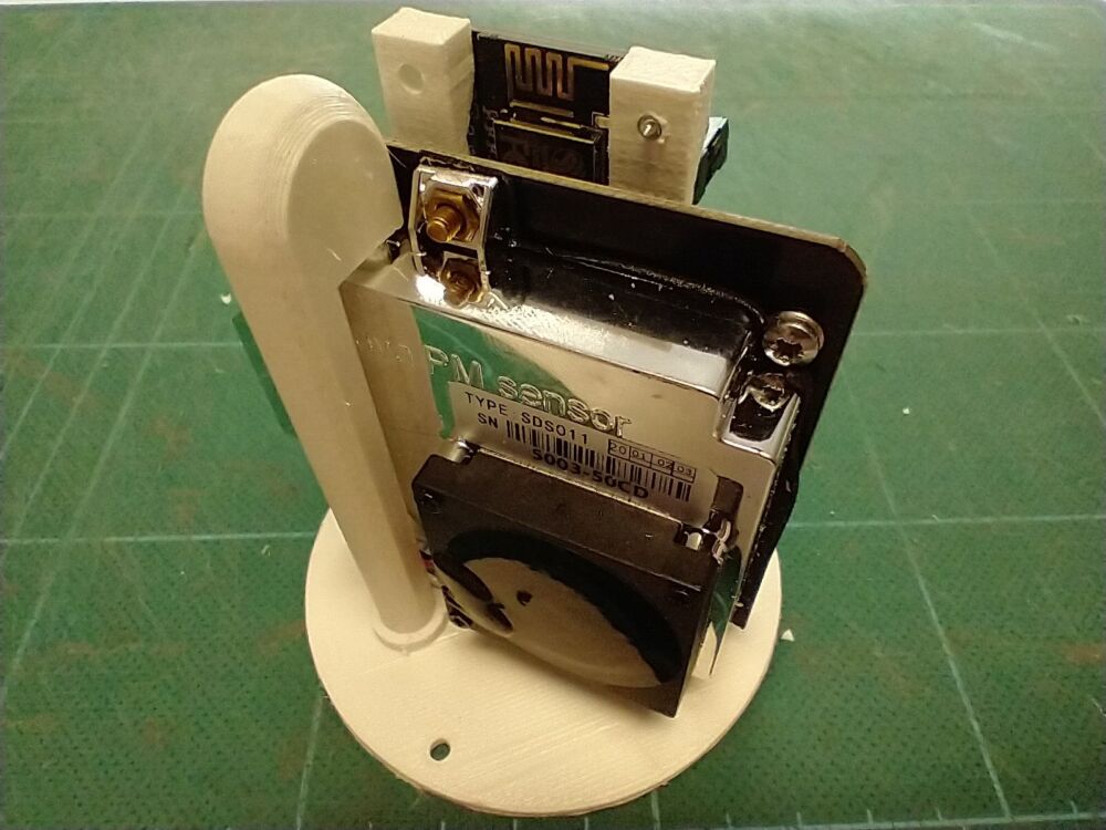
The exhausted air from the sensor comes out at the bottom of the laser sensor, and can escape to the world via tiny holes in the base.
The connections to the laser sensor are at the bottom and need to be routed through the gap in the middle of the frame:

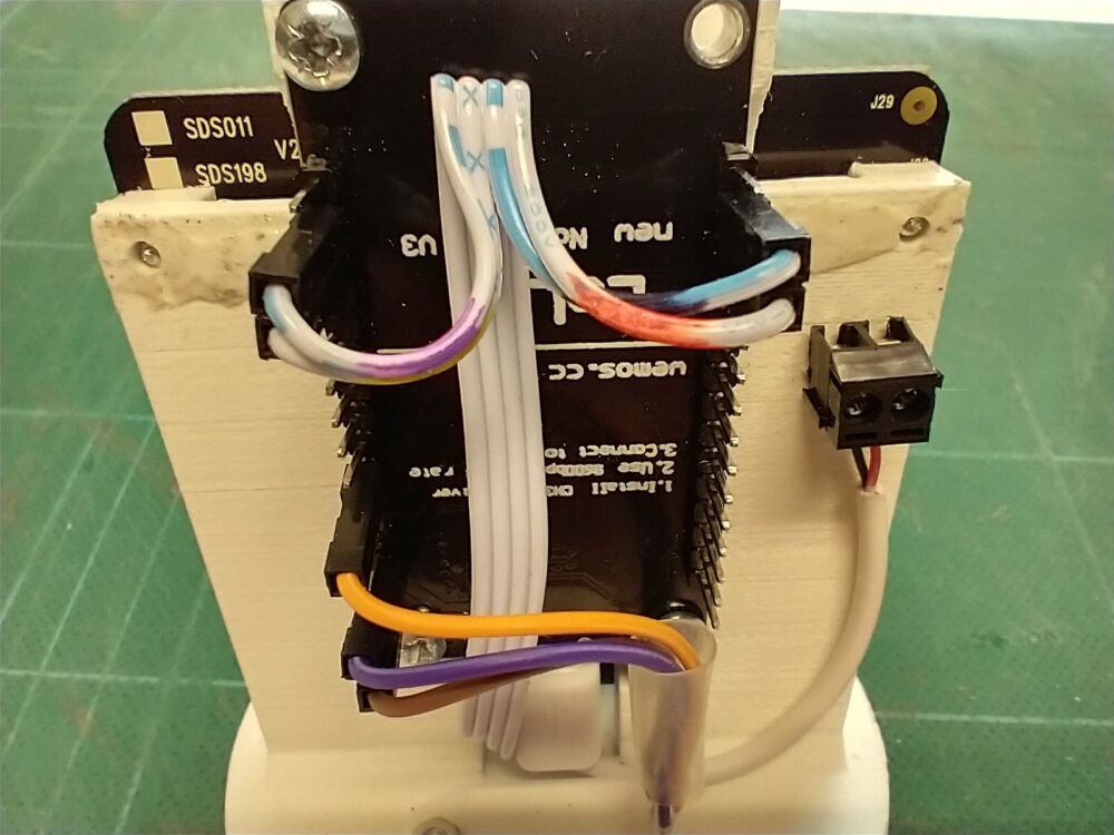
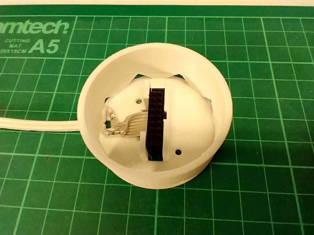
The controller board mounts on the other side, and is connected with useful push on connectors:

The top right hole in the computer board is used for a small cable tie to restrain the power cable.
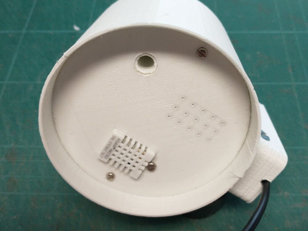
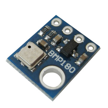
The DHT22 sensor measures temperature and humidity, and is mounted on the bottom of the case. It pokes through the bottom of the board so that the sensor is exposed to the outside world: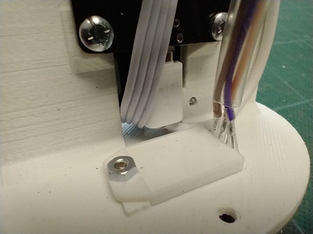
The unit will be powered from a long USB lead, which goes through the mounting bracket into the case. Once the unit is installed, it will be connected to the terminal block on the right of this photo:
This is the underside of the case with everything fitted; you can see the small exhaust holes and the temperature/humidity sensor:
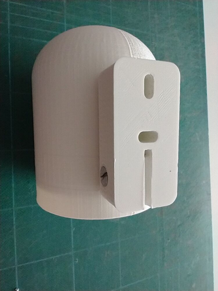
I designed a bracket to fit the case, this has two mounting holes to screw it to the wall and a path through it for the power cable:
I tested the system by temporarily mounting on the garage next to “my” sensor:
Once the unit settled down, they both gave very similar readings so I’m happy that everything works as planned.
You can see the readings from this sensor here: opensensemap.org/explore/60e478f616d878001b1df5f0 – You’ll need to click on the US flag on the top line and select English unless you want the text to be in German.
However, note that the sensor is currently disconnected, but should be up and running in a week or so. The sensor is also shown at the location where it will be eventually installed. The site does have useful descriptions of what PM10 and PM2.5 actually mean and there are plenty of other sensors to explore.
The Dimension Board Game is an interesting product, but not very well packaged to use the counters in the game. To make them simpler to store and use, I designed and 3D printed a couple of trays for the counters:

These stack on top of each other in one of the compartments in the box:

If you’ve got access to a 3D printer, you can print your own trays using the files here: Dimension Counter Trays STL
You need one of each as one tray has four compartments, the other three.
I’ve added an air quality monitor to my weather station. This uses a laser to measure the particle concentration between 0.3 to 10µm in the air. The sensor is the silver and black unit at the left, and has a small fan which sucks the air in from the outside via a small tube which you can just see going through the garage wall to the outside.

There is a more detailed explanation of the sensor Here
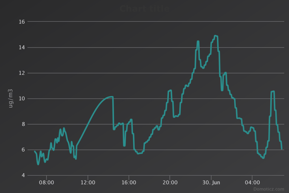
The output from this sensor are two values for PM2.5 and PM10, both measured in µg/m³. This graph shows the PM2.5 value for the last 24 hours – it’s still a bit high as the unit is still settling down:
You can see the results from this, and my other weather sensors, by viewing http://home.wsn.uk:5555 username ‘view’, password ‘view’. Click on the icons to see the graphs showing these inputs change.
See A Weather Station for the original post on this project.
I needed to create some fittings to hold some 12V LED lights used for emergency lighting, which was a good excuse to do a bit of 3D design and print them on the 3D printer:
The slot in the middle is for a connector for the lamp, which fits in from the back:
The 12V lamp then plugs into the socket:
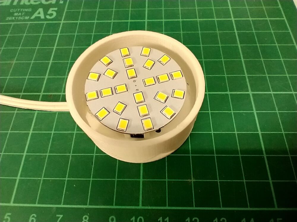
Note the gap around the lamp and the triangular holes to help airflow; the first version didn’t have these and the lamp got so hot that it melted the plastic of the base!
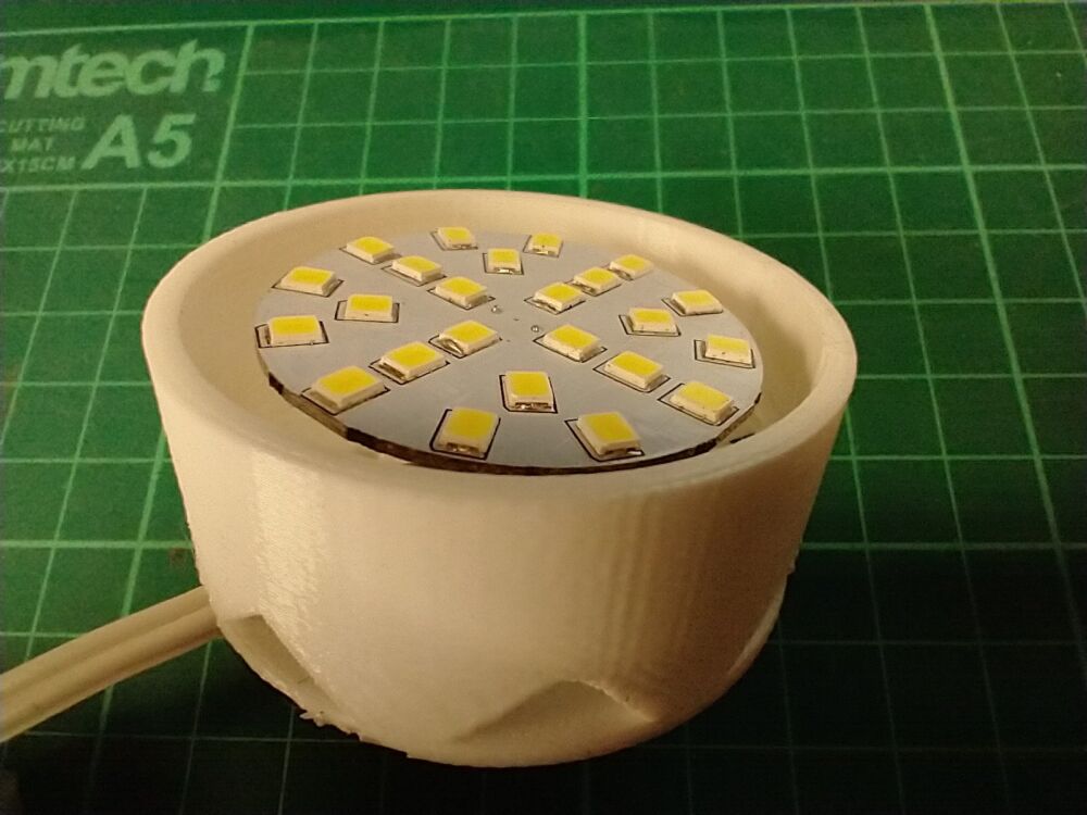
And finally, the working fitting. This will be mounted upside down on the ceiling:

We have an underground storage tank, which was used for irrigation when the surrounding area was an orchard before the house was built. It’s not as deep as it used to be, but still holds around 2000 gallons of water when full. It’s filled from half of our house roof, and all of the garage roof. There is a submersible pump in it which we use to water the garden.
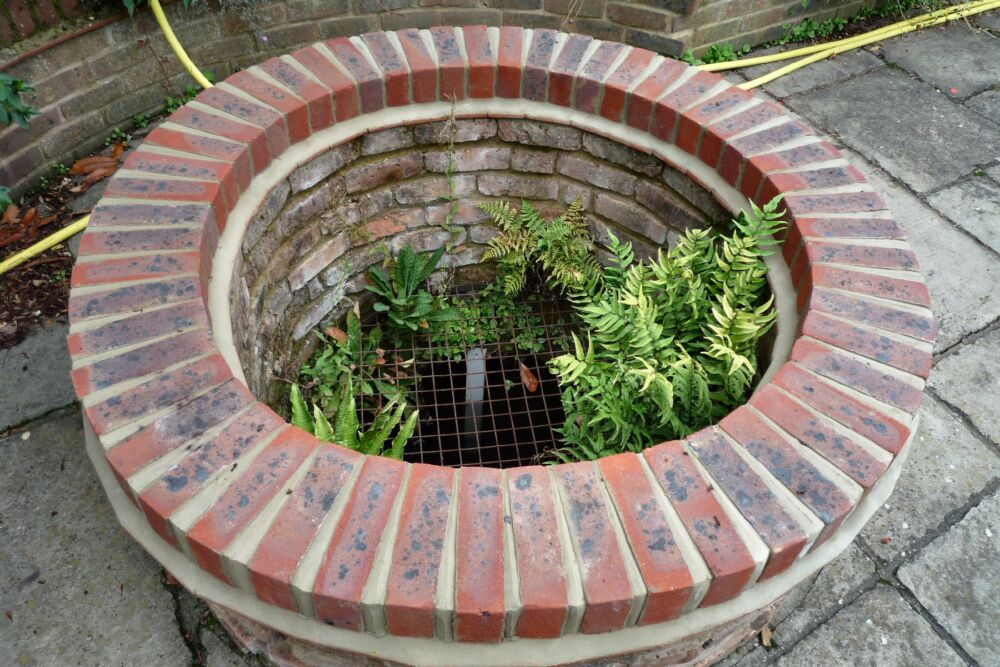
Measuring the water depth has always been a challenge, and you can just see a white measuring stick – but all the markings on this faded over time!
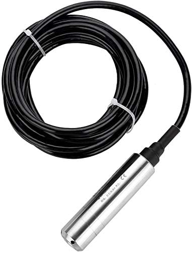
Last year, I purchased an ultrasonic depth sensor which worked fairly well but wasn’t robust enough to survive outdoors.
So this year, I bought an industrial pressure sensor, which now sits at the bottom of the tank:
I found an small microcontroller board that has a suitable input for this – this board also has integrated WiFi so it can send the measurements back to the house.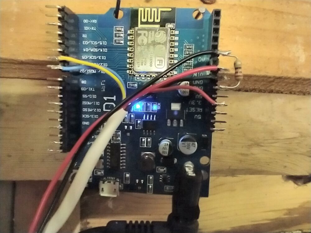
This sends the data to some logging software running on our Raspberry Pi based server.
This works just fine, but being a pressure sensor, the recorded level varies slightly with atmospheric pressure changes. So a bit more digging found this little board, which measures barometric pressure and temperature:
I found a design for a small “Stevenson Screen” to hold this board, which I printed on my 3D printer:

This also connects to the WiFi board.
You can see the results from these sensors by viewing http://home.wsn.uk:5555 username ‘view’, password ‘view’. Click on the icons to see the graphs showing these inputs change.
The next task is to adjust the Water Level reading with atmospheric pressure!
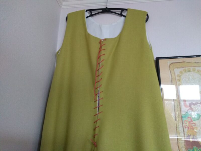
Having finished the construction of the kirtle itself, I then had to deal with the lacing; making the holes down the front was easy enough…
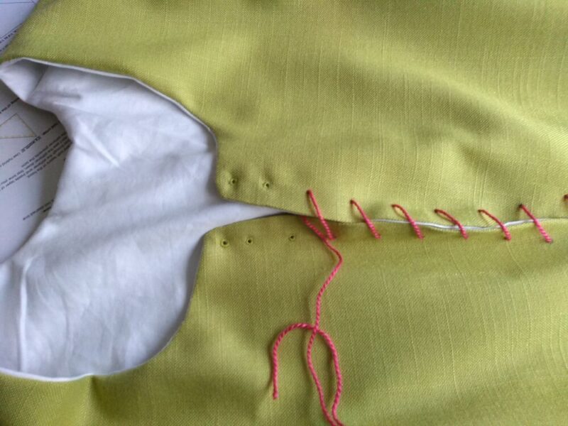
… but then the eyelets had to be hand stitched. This was extremely fiddly!
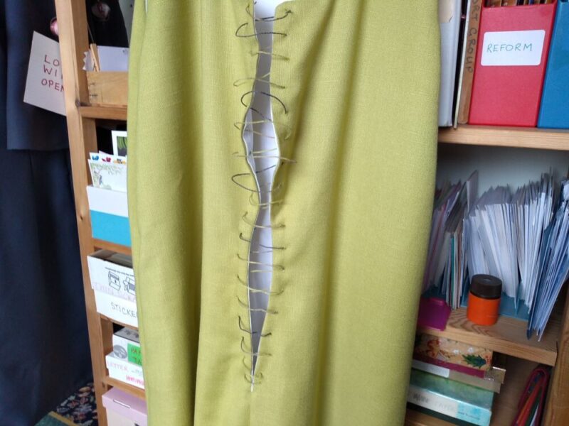
They weren’t too bad when I had finished, but they were rather too small, so I had to lace them with embroidery thread rather than cord. However, once it was waxed, as per instructions from Gemma, it was more or less acceptable.
Meanwhile, I began making a coif. This was made out of unbleached calico, which was what I had, and entirely hand stitched, which I was rather proud of!
And so the medieval peasant costume is finished!

I will need to make a more appropriate undergarment at some point, rather than a 20th century thermal vest!!
As usual, I don’t wait to finish one project before starting another; I was inspired by Pastime Historical Dance activities to make a 15th Century kirtle. Having got Phil to help with the measurements – it’s hard to measure your own back, I first drew the pattern shapes on to the last remaining length of some old cotton sheeting.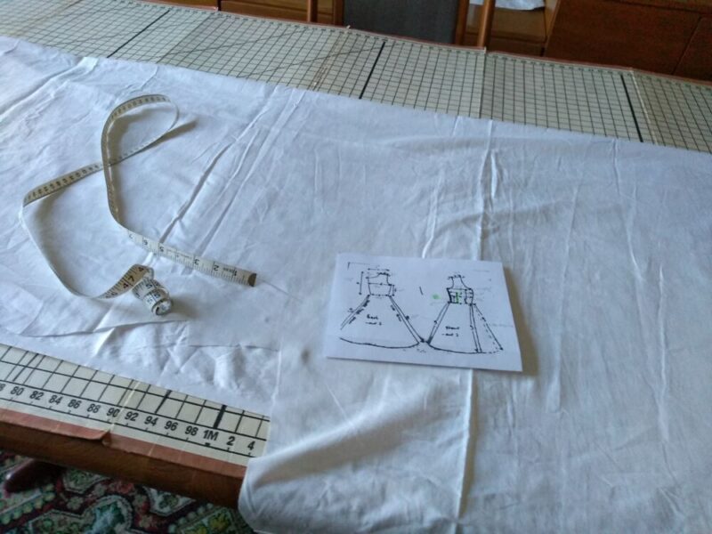
This was quite a challenge, as I am not exactly the shape anticipated by the sketch (ahem), but eventually I got the pieces cut out. The bust looked a bit odd, though.
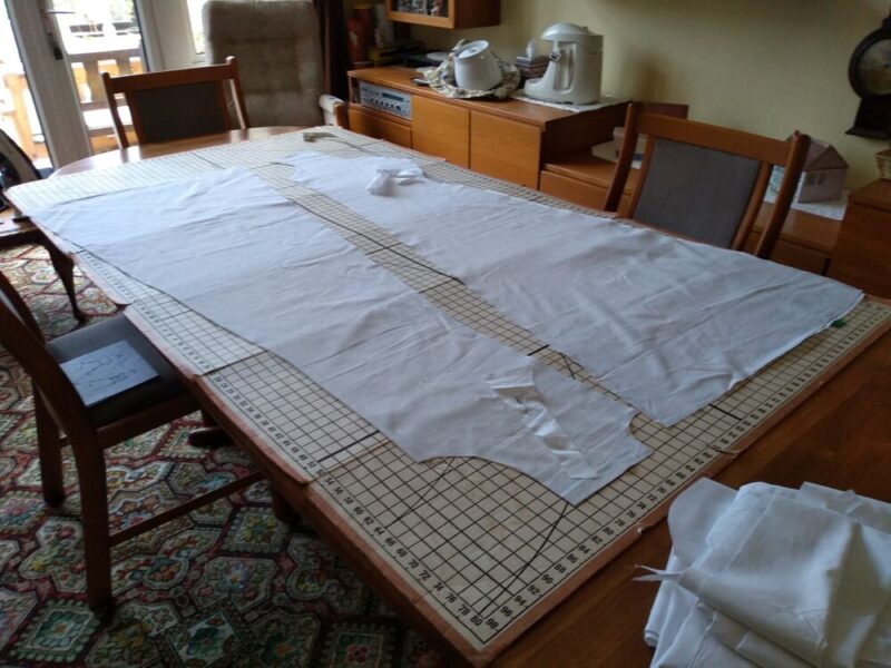
Having done a rough fitting, and adjusted said bust, I cut out the pieces from the main fabric.

The next step will be to stitch the pieces together!
That undergarment is a (fairly) modern nightie – my Tudor chemise is too bulky to fit under. That’s a problem for another day.
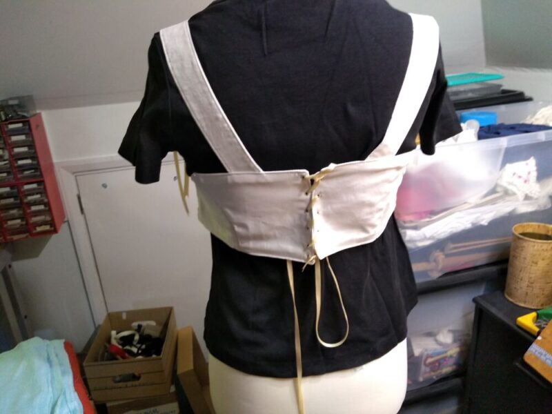
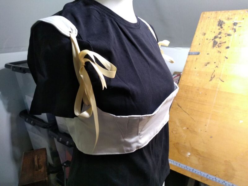
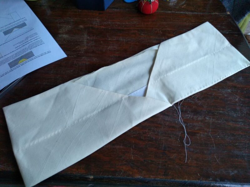
The last phase of making the stays was the eyelets for the lacing, for the shoulder straps and back fastening. I was pleased to find that my small hole punch went through the layers of fabric and interfacing. Stitching them was strangely therapeutic!
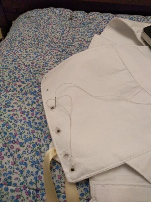
So, they are now done. I will have to make another chemise to go under them. Black t-shirt definitely not authentic! Although they look baggy on the dummy, they are fine on me since I am rather fuller of figure…